Category Archives: Fiero

Extended wheel studs for the 1988 Fiero

With aftermarket wheels and/or thicker brake rotors, the Fiero’s stock wheel studs don’t provide much thread engagement with the lug nuts. I found that on the front of my ’88 Fiero I was only getting 8 turns with the C4 12″ rotors and my Motegi wheels. That’s 12 mm of thread engagement on a 12mm stud. Marginal at best. With the 3mm spacers I wanted to add behind my rotors to get some control arm clearance, I would be down to a dangerous 6 turns or 9mm.

I scoured the ARP and Dorman catalogs to find a good candidate. The 1988 front hub holes are about 0.490″ with the stock studs removed. Dorman recommends a hole size between 0.017″ and 0.027″ under the knurl OD, while ARP recommends 0.005″ for iron and steel hugs and 0.007″ for aluminum. It’s not clear why there’s such a big range or difference between the recommended interference.

The closest longer studs that would fit are ARP 100-7708 and Dorman 610-323. The ARP 100-7708 studs have an 0.509″ knurl,  making a 1/2″ reamer the closest common size to the correct hole size (0.504″ by ARP’s recommendation). When installed, these studs increase the thread length by 0.84″ (21.4mm) over the stock studs.

The Dorman 610-323 studs have a 12.80 mm (0.504″) knurl, which fit in the original hub holes based on Dorman’s specifications. They are 54 mm long, thus increasing the thread length by 12mm over the stock studs.

I pressed the lug studs out of a brand new Rodney Dickman 88 front hub and measured the hole size as about 0.490″ at the smallest and around 0.50″ at the largest. I went ahead and pressed the ARP studs in without reaming the hole to 0.503″,  and they pressed in without too much trouble. The hub didn’t split, but a few metal shavings were produced by the knurl pushing through the hole. This fit exceeds the ARP recommendation for the interference fit, but is within spec if Dorman’s recommendation is followed.

1988 Fiero hub with ARP 100-7708 studs installed

Since these studs are so much longer than stock, open-ended lug nuts must be used. For GM wheels the stock ones should work. In the aftermarket, I found some inexpensive Gorilla lug nuts on Amazon.com. The part number is 20033SD for a set of 20 lug nuts and the spline drive socket. These nuts are narrow enough to fit in aftermarket wheels. I tried some White Knight lug nuts but they were too large in diameter to fit in the lug but counterbores in my wheels.

I purchased these inexpensive Gorilla brand  open-end lug nuts on Amazon.com
I purchased these inexpensive Gorilla brand open-end lug nuts on Amazon.com. p/n 20033SD

The Gorilla lug nuts fit perfectly in my aftermarket Motegi MR116 wheels. The only disadvantage of these nuts is that the require the use of Gorilla’s spline drive key. Some hex drive lug nuts are available from Vorshlag that look like they might fit, since they are small enough to use a 17mm hex instead of the 19mm hex on the White Knight lug nuts that were too large for my wheels.

After installing the extended studs and open-ended lug nuts, I had plenty of thread engagement while running a 3mm rotor spacer

The same studs will work just as well on the rear bearings as on the front.

Fiero Harness Bar

IMPORTANT NOTE: I am not a professional safety equipment builder, and I do NOT recommend building your harness bar the same way I built mine! This bar isn’t legal for any wheel-to-wheel racing, and race harnesses are not legal for use on the street. I just needed a way to put harnesses in the car for autocross and track days, since there’s no way to lock the stock seatbelts on a Fiero. Use a professional race shop to build a roll bar/cage if you intend to use a race harness. Race harnesses, harness bars and roll bars are NOT to be used on the street.

I recently finished building and installing a harness bar in my ’88 Fiero. I designed it so no parts need to be removed from the car except the B-pillars, the stock seatbelt can still be used, and no holes need to be drilled in the chassis.

Existing holes in the b-pillar can be used to pass bolts through for the harness bar.

I designed a bracket to go over two existing holes in the B-pillar. I mock up all my brackets in cardboard, then trace them onto the material to be cut on a bandsaw, and bend it using my vice and a hammer or adjustable wrench. Obviously a sheet metal brake would be a lot easier and more precise, but I don’t have room for one in my shop right now.

This is a mockup of the backing plate which goes on the inside of the B-pillar. It will have two M12 nuts welded to it for attaching the harness bar.

There is a hole at the bottom of the B-pillar that’s big enough to fit my arm through to feed the inner backing plate into place. I had two M12 nuts welded to the backing plate so I don’t have to fumble with nuts on the inside.

I bent the harness bar from 1.5″ OD, 0.120″ thickness 4130 “chrome moly” steel using a JD Squared Model 32 manual bender:

The harness bar cross beam was bent using a JD Squared Model 32 manual bender.
The harness bar cross beam was bent from 1.50″ OD 0.120″ wall thickness 4130 “chrome moly” steel tubing using a JD Squared Model 32 manual bender.

Schroth shoulder harnesses

The brackets (inner and outer) were cut from 3/16″ 4130 steel plate and bent in my vice:

The brackets are made from 3/16" thickness 4130 steel plate. They were cut on a bandsaw and bent on a vice. Precise fitup is extremely important for strong welds with 4130. There should ideally be NO gap between the tube and bracket plate.
The brackets are made from 3/16″ thickness 4130 steel plate. They were cut on a bandsaw and bent on a vice.
Precise fitup is extremely important for strong welds with 4130. There should ideally be NO gap between the tube and bracket plate.

I may add another M8 or M12 bolt in the 3rd hole, but haven’t done so yet.

Anti-rotation brackets mockup
Anti-rotation brackets can be tied into the harness bar by welding in additional tubes. This can help prevent the main harness bar from rotating forward when the shoulder harnesses pull on it in a collision.

If anti-rotation bars are desired, the main harness bar can be tied into plate bolted to the OE shoulder belt mounting points.

The bracket shown mocked up in cardboard would be made from 3/16″ 4130 steel plate and would be tied into the main harness bar with 1.5″ OD 0.120″ wall thickness tubes. This can help prevent the main harness bar from rotating forward when the shoulder harnesses pull on it in a collision.

When I have enough parts ready to fill a large batch, I’ll probably have the harness bar powdercoated. I’ve read that some race teams don’t powdercoat or paint their roll cages or harness bars, so that it’s easier to inspect for cracks. However, some surface rust will develop over time if it isn’t protected.

Repairing Fiero Coolant Tubes

With its mid-engine layout, the Fiero needs to shuttle coolant from the rear to the front of the car, where the radiator is located. The coolant flows through tubes located just inboard of the rocker panels. Since this is a common location for modern cars to be lifted for maintenance and repair, shops often damage the coolant tubes by using them as jackpoints. All it takes is one careless mechanic or tire shop employee to crush the pipes and render the cooling system ineffective.

The damage is often hidden, as shown below:

Damaged coolant pipe, viewed from below
Damaged coolant pipe, viewed from below where the damage is not visible
The same pipe, removed and viewed from above
Damaged coolant pipe, viewed from the side

Replacement coolant tubes for the 1984 to 1987 Fieros are available from The Fiero Store. However, they are expensive, and tubes for 1988 Fieros are not available.

With access to a welder, it’s possible to repair kinked/crushed tubing.

First, cut the tubing at the narrowest part of the kink. A hacksaw will make quick work of the thin stainless steel tubing.

Coolant tubing cut into two pieces at the narrowest part of the kink
In the cross-section, you can see the magnitude of the restriction. This tube had about 30% less cross sectional area than it should have. It wasn’t enough to cause overheating in normal driving, but on the track coolant temps were very high.

When not suffering from damage, the coolant tube should have an inner diameter of ~1.236″. A socket with approximately the same outer diameter can be used as a mandrel to bend the tube back into shape.

A 1/2"-drive socket with the right outer diameter can be used as a mandrel to reshape the coolant tube
A 1/2″-drive socket with the right outer diameter can be used as a mandrel to reshape the coolant tube. This socket has a stepped region with a smaller diameter so it fits in the bent tube.

To facilitate removal, insert a long bolt through the drive hole in the socket. Later, a slide hammer can be used to remove the socket.

Insert a bolt through the socket and install a nut so it can be used to pull the socket. A nylock nut was used here to prevent it from accidentally loosening during removal.

It may be necessary to bend the coolant tube with pliers or a vice to make room for the stepped smaller diameter of the socket.

It will be necessary to secure the coolant tube in a vice to prevent it from moving while knocking the socket into the tube.

After making the small diameter of the socket fit by bending the tube with pliers or the vice, carefully hammer the socket evenly into the tube. Make sure to wear safety glasses! The chrome plating of the socket or the hammer itself may chip. Using a piece of wood to drive the socket is also a good idea, as it can help prevent the hammer and socket from chipping, and help distribute load.

After the socket is fully inserted into the tubing, remove it using a slide hammer or channel locks (see photo below).

If you don't have a slide hammer, grab the bolt with channel locks and use it to remove the socket.
If you don’t have a slide hammer, grab the bolt with channel locks and use it to remove the socket.

Repeat the socket-reshaping procedure described above fro the other piece of the cut tube.

This Fiero coolant tube has been reshaping by hammering a socket into it.

Finally, prepare the tube for welding by sanding the inside and outside, and grind or deburr the faces if necessary to get the best fit.

This tube was welded back together using a TIG welder and stainless steel filler rod.

If you don’t have access to a welder, a muffler shop should be able to weld the tube back together. Make sure they know it’s stainless steel, and tell them to line up the welded seam of the tubing.

Autocrossing the DOHC V6 ’88 Fiero – Part 2

I previously wrote about my first experience autocrossing my DOHC V6 Fiero. On March 9th and 10th I participated in the Evolution Performance Driving School Phase 1 and Phase 2 courses. It was my first outing since making a significant number of changes to the car to fix the oversteer problems that I encountered the first time.

Notable changes since last time include:

  • 400-lb/in front springs
  • Fieroguru’s lateral link relocation brackets
  • New alignment
  • Revised lateral link lengths
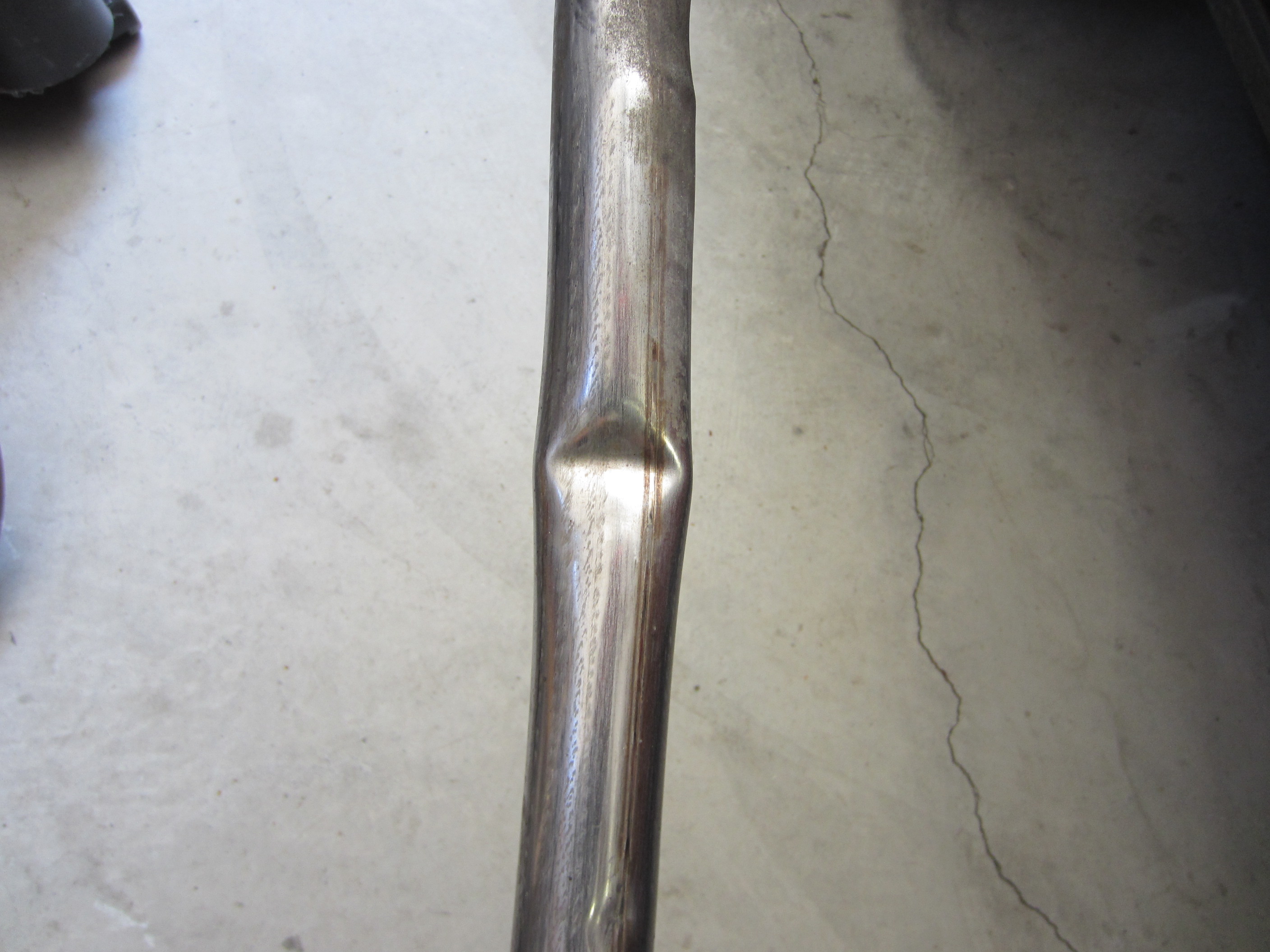
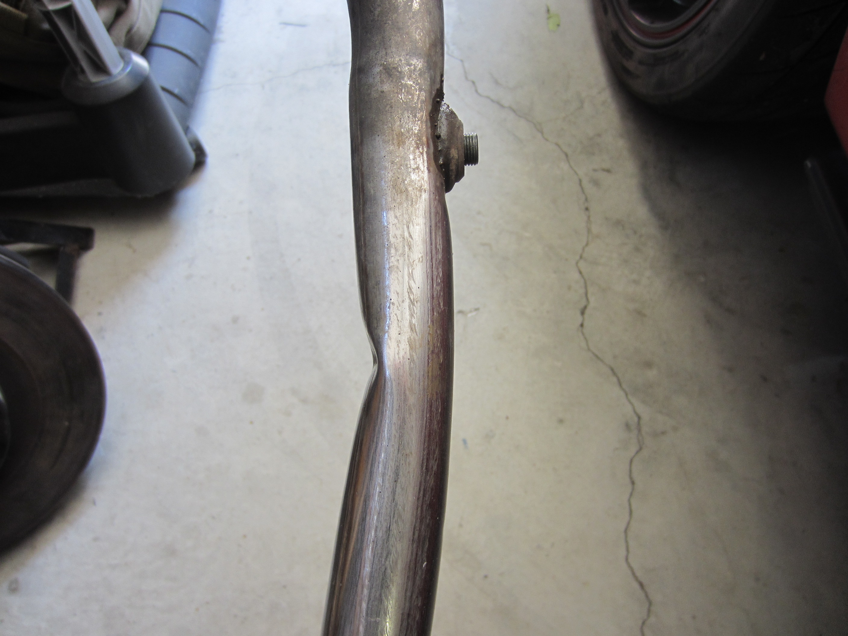
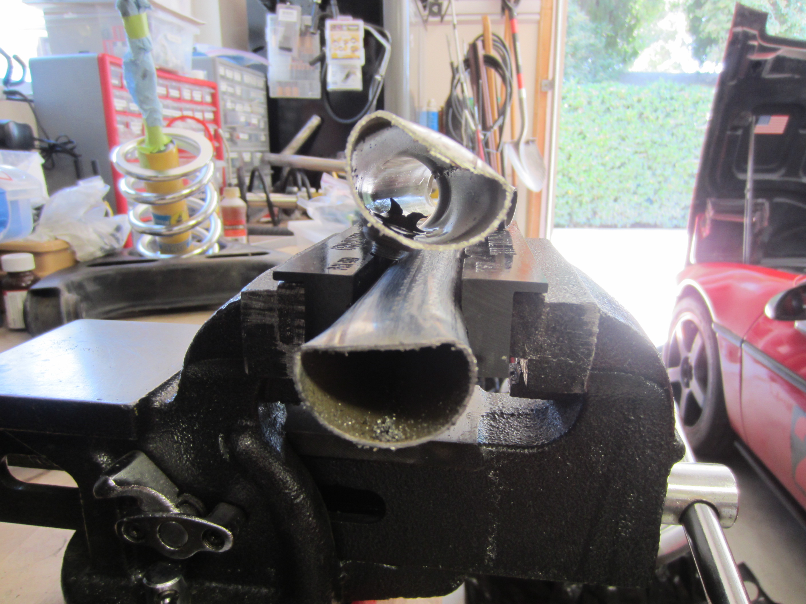
  • New exhaust system
  • New clutch, new steel flywheel (I had continual problems with the aluminum one loosening up)

I also weighed the car (see below).

Setup

Tires/Wheels

  • Front: 17×7 (48mm offset) Motegi MR116, 215/45/17 Hankook RS3
  • Rear: 18×9 (45mm offset) Motegi MR116, 275/35/18 Hankook RS3

Alignment & Ride Height

  • Front toe in: 0
  • Front camber: -1.1 deg
  • Front caster: Mechanical maximum (I didn’t measure)
  • Rear left camber: -1.8 deg
  • Rear right camber: -2.3 deg
  • Rear toe in: 0
  • Front ride height: 13.9 inches (fender arch to wheel center)
  • Rear ride height: 14.6 inches (fender arch to wheel center)

Weight (NEW!)

All weights are in pounds.

Without driver With 140-lb driver
Total 2779 2920
Left Front 604 655
Right Front 579 595
Left rear 780 833
Right rear 816 837
Cross 48.9% 48.9%
Left 49.8% 51%
Right 50.2% 49%

Shocks/Springs/Bushings/Etc

  • Front springs: West Coast Fiero 400 lb-in with ~1/2 coil removed
  • Front shocks: Koni Red, adjusted somewhere in the middle
  • Front swaybar: Stock, with Rodney Dickman’s solid endlinks
  • Front bushings: Polyurethane everywhere except the swaybar mounts are stock
  • Rear springs: 350 lb QA1
  • Rear struts: Koni reds, adjusted somewhere in the middle, flipped strut top mounts for more compression travel
  • Rear swaybar: None
  • Rear bushings: Poly on the trailing links, solid rod end lateral links
  • Other: fieroguru lateral link relocation kit (lowers outer end of lateral and trailing links by 1.5 inches)

Weight reduction/relocation

  • Front mounted Miata battery (23 lbs), mounted behind the front crossmember
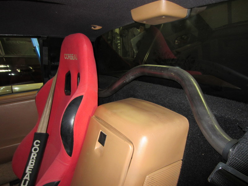
  • Corbeau A4 seats on original Fiero sliders
  • Removed jack, wrench, spare, and spare tire tray

Engine

  • Balanced and blueprinted 1993 3.4 DOHC V6, modified short runner intake manifold
  • 220whp on the Dynapack at Church Automotive

Transmission

  • Fiero Getrag case with later Getrag 282 internals (slighter shorter 5th gear, larger and stronger diff)
  • Clutchnet organic/clutchtex disc and “yellow” pressure plate with stock steel flywheel
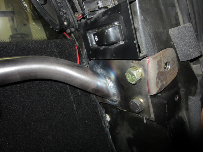
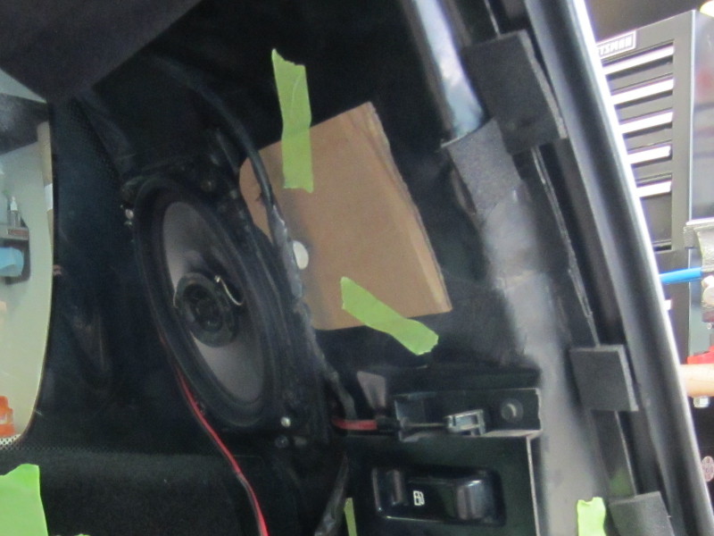
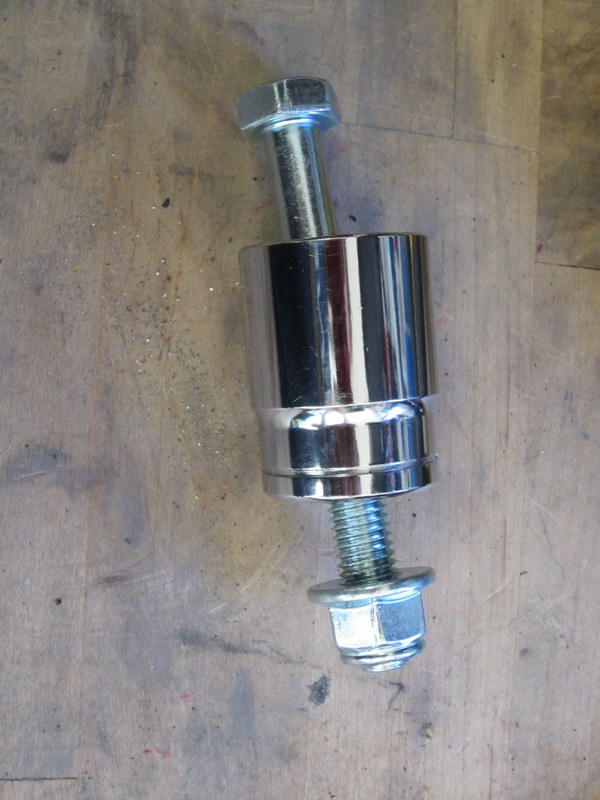
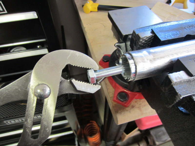
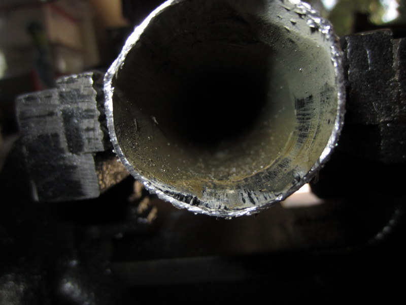
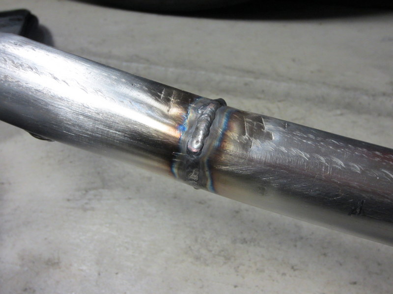
Exhaust

  • Stock exhaust manifolds and crossover, 2.5″ cat, Magnaflow 2.5″ single-inlet dual-outlet muffler, resonated tips

Brakes

  • Slotted/drilled 12″ Corvette rotors
  • 88 Fiero calipers
  • Porterfield R4-S pads
  • OEM-style rubber brake hoses

Steering

  • 2-turns lock-to-lock power steering rack from a C4 Corvette ZR1 or Z51 package

Handling Impressions

Wow! With the new tires and suspension modifications the handling is MUCH improved. There is no more tendency to oversteer into instability when tightening up a turn, even when applying power. Yet the car does not plow. It’s VERY neutral.

The car received nothing but praise all day. Even the Evolution Performance Driving School instructors were impressed with the car’s handling. They all commented that the car didn’t have any weird habits, and was fast and fun to drive.

My run times were indicative of a massive improvement in performance. Rather than lagging seconds behind my friends’ Honda S2000 (also running Hankook RS3s), I was running neck and neck with him.

Rather than being afraid to push the car due to it’s previous tendency toward terminal oversteer, the handling now inspires confidence and feels very consistent and predictable. I felt like I could push the car to the limit of my ability.

You can check out a video of one of my runs here: https://www.youtube.com/watch?v=we8JNa_KOxk

Why it’s better

The new tire sizes slightly increase the rear grip bias. Previously, I had the tires staggered with 205s up front and 255s in the rear, giving a tire width distribution was 44.6% front / 55.4% rear. With the new 215/275 setup, the distribution is 43.9%/56.1%. Actually, the rear grip bias is even higher than that because I went to a smaller diameter tire up front and a larger one in the rear, further decreasing and increasing the size of the contact patches respectively.

The stiffer front springs increase weight transfer to the front while cornering. This is certainly a factor in the new handling of the car.

Possibly the most significant change besides the tires is the addition of the fieroguru lateral link relocation brackets. With these brackets, the two lateral links and trailing link on each side have their outer pivots moved down by 1.5″ inches.

These brackets have multiple benefits:

  • Increased roll center height (and thus less body roll)
  • Increased camber gain
  • Increased static camber

Even with my adjustable lateral links reduced in length to match the stock links, I was still able to obtain the same static camber settings in the rear as before. I could have added a bit more on the rear left to match the rear right, but I was pressed for time and didn’t want to mess with it.

I didn’t get any photos of my rear suspension in action like at the last event. However, based on the tire wear it looks like I’m no longer getting positive camber in the rear while cornering hard. Observers also noted that my car corners relatively flat, as I would have expected from the increased roll center height.

Next steps

Now that I have corner weights, I have enough information to have my shocks revalved, so I may do that soon. One of my front shocks is leaking, so I at least need to get it rebuilt.

I’ll plan to run the car at a few more autocrosses for more driving practice and to see how consistently it performs… then it’s on to the road course.

My friend took the car for a test drive and pointed out some high-speed handling peculiarities. After a few more autocrosses the next logical step is to get to a road course and sort those out. I currently suspect that one of the trailing links is loose or has soft bushings, causing a slight change in rear toe that’s only noticeable at highway speeds.